Overview
This recreation of Lunar Lander was programmed in Easy68k assembly over the course of two weeks. It features two different win conditions, physics, and a seven-segment display.
Implementation
Rendering
Rendering was accomplished by reading in a BMP file and, using its file header, extracting the necessary data to calculate the width and height of the image. From there, each individual picture was read in and drawn to the screen. As this process is costly, only the areas of the screen that had movement on top of them needed to be rewritten. This drastically sped up the program.
determineColor
        * Determine color
        move.l (a0), d1         ; move next color from memory into pen

        * Byte shift
        ror.l #8,d1             ; make sure all the bytes are in the right spots

        * If color is transparent, skip it
        cmp.l  #TRANSPARENT_COLOR, d1
        beq    skipDraw

        * Set color and draw pixels
        move.l  #PEN_COLOR_TRAP_CODE, d0    ; set the proper trap code to set the pen color
        trap    #15                         ; set pen color through trap code

        * Set location to draw
        move.l d3, d1           ; x location
        move.l d4, d2           ; y location

        move.l #DRAW_PIXEL_TRAP_CODE, d0    ; set trap code back to drawing pixels
        trap    #15                         ; draw pixel

skipDraw:
        * Loop incrementers
        addi.l  #1,d3                   ; increment width counter
        cmp.l   d3,d5                   ; compare loop counter (d1) to width (d5)
        bne     continueRow             ; continue loop
nextRow:
        move.l  d7, d3                  ; reset width counter for next loop
        subi.l  #1,d4                   ; decrement height counter
        move.l  THIS_OFFSET_Y(sp), d1
        cmp.l   THIS_OFFSET_Y(sp), d4   ; check if height has reached offset
        bne     clipX                   ; if it has not, continue

        * Return to caller
        move.l #4, d0
        sub.l d0, sp
        jsr loadAllRegs                 ; restore registers
        add.l d0, sp
        rts                             ; return from function
Physics
Physics was implemented using simple linear acceleration.
* Params: direction x, direction y
* Positive x -> right, positive y -> down
addVelocity:
* Math
    * Add x direction to velocity
    move.l  DIR_X(sp), d0           ; move var from stack to register
    cmpi.l  #0, d0                  ; if x velocty is 0, don't use fuel
    beq     skipFuelX
    subi.l  #1, (fuel)              ; subtract 1 from fuel
skipFuelX:
    muls    #ACCELERATION_X, d0     ; multiply acceleration by direction to get correct direction
    add.l   d0, (velocityX)         ; add acceleration to velocity

    * Add y direction to velocity
    move.l  DIR_Y(sp), d0           ; move var from stack to register
    muls    #ACCELERATION_Y, d0     ; multiply acceleration by direction to get correct direction
    cmpi.l  #0, d0
    beq     skipFuelY
    subi.l  #1, (fuel)              ; subtract 1 from fuel
skipFuelY:
    add.l   d0, (velocityY)         ; add acceleration to velocity
The challenging aspect of implementing it, however, was in converting integers to floats. x86 Assembly, storing only bytes of information, does not have any inherent method to represent floats. Instead, fractional bits were used. Essentially, depending on how accurate I wanted my float to be, n fractional bits were reserved as the last n bits of the longs I used. Then, any math could be applied to those drawn out numbers, and the fractional bits can be shifted back when the number needed to be used as an integer.
    * Add velocity parameters
    move.l  #12, d1             ; set space for parameters
    sub.l   d1, sp              ; set up SP
    move.l  d5, (sp)            ; move values onto stack
    move.l  d4, 4(sp)
    jsr     addVelocity

    * Get x result
    move.l  (velocityX), d5     ; move velocity into register
    add.l   d5, d6              ; add it to position

    * Get y result
    move.l  (velocityY), d5
    asr.l   #FRAC_BITS, d5
    asr.l   #FRAC_BITS, d5      ; shift d5 back
    add.l   d5, d7              ; add y velocity to position
    add.l   d1, sp
Win Conditions
Two win conditions and one lose condition were present in the game. The player could safely land on yellow segment for 1 point or on the green segment for 2 points. If the player had a velocity above a certain amount when they landed or landed in a different area, they would die and be sent to the start of the game. Win conditions were calculated based on the color of the pixel directly below the lunar lander. If the hex code of the color matched one of the winning colors, the player would gain a point and return to the main menu.
checkForWin:
    cmpi.l  #WIN, (gameWon)         ; if game was not won, it was lost
    bne     gameEndLose

gameEndWin:
    * Check for extra points
    cmpi.l  #1, (extraPoints)
    beq     showExtraPtsScreen      ; if extra point win, go to extra point screen
    bra     showWinScreen           ; if regular win, go to regular win screen
gameEndLose:
    jsr redrawBackground
    jsr drawSpriteBroken            ; draw broken sprite if lose
    jsr swapBuffer
Seven Segment Display
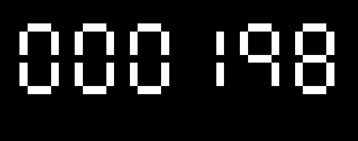
A seven segment display has one main advantage over using sprites to represent numbers: it is a lot faster. Lines being drawn instead of entire images that needed to be read in before even beginning to be drawn shaves off a ton of time. For implementing this, I stored a table to show the coordinates of every line in a single digit based around the lower left corner. Figuring out exactly how I wanted to do that took a few attempts and more than a few sketches.

segmentTable:
    dc.b $3F    ;0
    dc.b $06    ;1
    dc.b $5B    ;2
    dc.b $CF    ;3
    dc.b $66    ;4
    dc.b $6D    ;5
    dc.b $7D    ;6
    dc.b $07    ;7
    dc.b $7F    ;8
    dc.b $67    ;9

ledPositionTable
    dc.l $00010003 ; a = (1,0) -> (3,0)
    dc.l $01040304 ; b = (4,1) -> (4,3)
    dc.l $05040704 ; c = (4,5) -> (4,7)
    dc.l $08010803 ; d = (1,8) -> (3,8)
    dc.l $05000700 ; e = (0,5) -> (0,7)
    dc.l $03000100 ; f = (0,1) -> (0,3)
    dc.l $04010403 ; g = (1,4) -> (3,4)
Once I figured out how I wanted to store each of the lines, drawing them was deceptively easy. To get each digit by itself, I used x86’s version of modulus. Then I looped through each number, and each segment of each number. After that, I used x86’s trap code for drawing a line given two coordinates.
